3D Voronoi Shattering on GPU
I have worked on this project during my master’s thesis (original source, a short paper). I wanted to somehow expand the physical simulation so I have moved from rigid body simulation to brittle body simulation (considering convex objects only). Another update was moving most of the computation to the parallel GPU environment. Again, this is not a step by step tutorial but rather an overview of what I have learned from this project and what I think might be useful for some people crawling in the depths of the Internet.
- Why and how on GPU?
- Random points generation
- Voronoi and BCA algorithm
- Dividing the model
- N-th nearest neighbor
Why and how on GPU?
Nowadays many engines are moving the physics on GPU. The point is that you have the geometry of your 3D models on GPU anyway for rendering so why not exploit this and actually do more, also minimizing the GPU <-> CPU communications which is quite costly. This allows us also to get a lot of free CPU time for AI and other stuff needed for games etc. So in other words the geometry, object information (position, velocity, mass…), bounding boxes, scene representation structures and trees, physics computation, collision detection, draw commands, all that is stored/computed on GPU.
There are many attempts to make the communication optimal such as indirect multi draw commands in OpenGL (basically you draw the whole scene using one API call). As for the GPGPU usage (using GPU for non-rendering computations, general purpose), OpenGL offers so called compute shaders where you can run your own kernel (a piece of GLSL code).
The threads running on GPU (kernel invocations) are computed within workgroups. In the workgroup the threads are at the HW level divided into warps/wavefronts that are being computed on one streaming multiprocessor simultaneously. In order to synchronize the threads within one workgroup, most of the libraries offer barriers which stop the threads until all of them reach the barrier point. It's also possible to use atomic operations to keep the global or local memory valid in case of multiple read/write operations. Each workgroup is assigned to one streaming microprocessor which allows all its threads to work with a local on-chip memory which is faster but much smaller than global memory. It's advised to use it for caching and local workgroup data. I am not going to talk about GPU too much here so check out the resources for some useful links.

Random points generation
Since there are no random generators on GPU, it’s up to the programmer to implement one. There is a well-known pseudo-random method exploiting the high frequency sinus floating point error. Here is the code:
A = 12.9898;
B = 78.233;
C = 43758.5453;
fract(sin(dot(coord.xy ,vec2(A,B))) * C);
What do we need now? To get some random points inside the geometry. Each random point will be a center of one fragment after shattering therefore their distribution defines how will the shattering look like. We probably want to make it more dense around a contact point (when I drop a teacup, more shards will be around the point where it hits the ground). One way would be to model an inverse probability distribution function for example using a tangent, having the shallow part of the function around the contact point in each of the xyz axes, generating each coordinate separately in AABB.
Points generated outside the model however might cause problems later. We can either fix it by moving inside or eliminate them. Is there a way to generate the points inside the model right away without the need to generate a point, check if it’s inside and move it inside/try again? There is, even though it’s not perfect for some precise simulations. It works well enough for our purpose and convex objects with enough triangles. The approach is simple:
- Generate a random triangle index of the model
- Generate an random offset on one of the triangle’s line segments aka a point
- Do the same on a segment connecting the new point with the third triangle point (the one not on the segment from the second step), now we have a random point on the triangle
- here you can simply move the point inside the model, the easiest way is apply the same approach again on the line connecting the point we have with the geometry center

To make the points be closer to the contact point we can again either move them towards it (randomly maybe) or simply use the GPU parallelism, generate more points and simply pick with a defined probability the ones closer to the contact point.
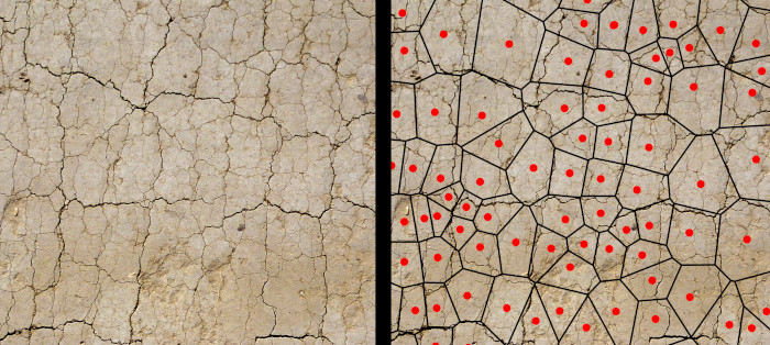
Voronoi and BCA algorithm
Now the main part. Voronoi diagram is a great tool to simulate many natural phenomena such as the shattering. Imagine a set of points (yea, the ones we generated) and now the space around them divided so that each point takes the closest area around that is closer to that particular point than to the others. That’s Voronoi. Since Voronoi is widely used structure, there are many good algorithms even for the GPU. The commonly used approach is the Delaunay based one, where Voronoi is extracted from a Delaunay triangulation which is kinda easier to construct. It’s possible to get the planes of the Voronoi cells from the triangulation.
OK, how would you get the actual cells from the planes? Looking for the intersections of the planes, getting the intersection lines and points, dealing with the floating point errors. Well in fact you can simply use the planes to cut the 3D model right away. Take the first plane, throw away the model triangles on the negative side of the plane, split the triangles that intersect the plane and triangulate the hole. Now repeat for all the planes. Simple but slow, resulting in too many memory accesses and the triangulation of the resulting fragment is ugly. For some reason I just wanted to come up with something new, my own approach (with a huge help of my supervisor). So let me proudly present you the so called (yea I tried to make it sound cool) Box Cutting Algorithm.
The advantages of BCA are that it’s intuitive and easy to understand, inherently parallel and the result is the actual cell geometry which is easily triangulated. One workgroup computes one Voronoi cell, each thread handles one line segment or vertex of the current cell shape plus some other elements when computing parallel tasks (which are almost all of the needed operations). Each WG works in a cell-space, the cell center (each previously generated random point corresponds to one cell center) is the origin, therefore a plane separating two cells can be represented as one vector where its direction is the normal and magnitude is the offset along the normal (position of the plane). The cell shape is defined by an array of vertices, planes and line segments (ids of two vertices and ids of two adjacent planes). It goes like this:
- Initialize the cell as a AABB of the model (it can be done in parallel when you number the vertices, lines and planes in a smart way so the index can be derived from a thread ID)
- Get the n-th nearest neighbor to our center (from the input set of points, n=0 in the first iteration). Stop if this neighbor is outside the sphere with two times current maximal distance radius (defined a few steps later).
- Get the plane between the center and the found neighbor
- Perform an orientation test on all the cell vertices against the plane (save in a bitfield)
- According to the result decide which line segment lies completely outside the new cell and remove it, split the ones intersecting the plane and leave the ones inside the cell (the plane cuts the box)
- Create a convex hull of the new vertices (the ones born during the line segments splits, note that there is no need to use any classic convex hull algorithms since we have the information about the adjacent planes in the lines so simply connect the new vertices of the split lines having the same adjacent plane). As a result we’re getting some new line segments.
- Get the maximal distance of the cell aka the furthest cell vertex from the center.
- Perform cleaning (avoiding sparse arrays by removing the dead vertices and lines since local memory on the GPU is limited).
- Go to the second step.
Here are some pictures. The first one is about the cell space. The thick shape is the model, the dashed one is the AABB and the dotted lines are the cell borders (lines in 2D, planes in 3D). s is the cell center, pn is a vector representation of the cutting plane and sn is the n-th closest neighbor. c is the model geometry center. The second picture describes the BCA steps and the third one the shrinking of the maximal distance.


OK so now we have the cells, let’s triangulate them (for each plane take the adjacent line segments and simply chose one vertex and connect it with the rest of the line segments). This is enough for a box model. What about other shapes?
Dividing the model
I’ve mentioned the incremental cutting of the model by the cell planes before but that is not an optimal way. So we have the model and we have the cell geometry. Now what we need to know is what part of the cell geometry can be triangulated and used in the final fragment, what part is outside the model and what part of the model’s surface is going to be a part of the fragment. The image below describes the problem. There is a model and Vornoi cell (thin line). What we want is their intersection.

Here is what we do:
- For each model surface triangle decide which is completely in the cell, which is intersecting a cell boundary and which is outside.
- The triangles outside the cell are thrown away, the ones inside will be simply copied in the final fragment geometry and the intersecting ones need to be split.
- Perform the splitting (might take multiple iterations per triangle because multiple cell planes might intersect the triangle, a BCA principle might be used to perform this splitting). Store the new triangles in a temporary array, they will be copied to the final fragment.
- Insert the plane of the slit triangle into the BCA and mark the plane as non-triangulated. This way we’re editing the cell shape to prevent it overlapping the original model surface that will be a part of the fragment. This plane will not be triangulated. (in fact we could have simply added all the model surface triangle planes in the BCA without any tests but that would be unnecessarily slow)
- When all model triangles are checked and processed, triangulate the cell faces and copy all the triangles (the original intact ones, the results of the splits and the triangulated cell faces) in the final fragment geometry.
- Create a new object info struct and add a new draw command.
The triangle splitting process and triangulation is described by this picture:

N-th nearest neighbor
How do we get the first, second, third nearest neighbor to a point given a set of points? Brute force? Too slow. This is actually the bottleneck of BCA algorithm. Searching for the n-th nearest point is the most expensive operation of the whole process. First I’ve tried to optimize it using a sphere tree (randomly choose two points, split the set according to the distance to those two points, choose randomly from the new sets etc.) which helped a lot, eliminating some parts of the tree, thus getting rid of some points to check. It’s possible to use an octree or some locally sensitive hashing methods as long as you can implement it optimally in parallel (we don’t want to have an optimization tree building time greater than the rest of the computation).
I was however really surprised in the end and I have realized how amazing the massive parallelism is. Sometimes a better approach is to actually use the brute force method, exploiting the parallel programming patterns and memory access optimizations instead of reducing the amount of computation like when programming a sequential algorithms on CPU. So what I used and what brought a rapid speedup was a thing called parallel reduction. The image below describes it (seriously, there are tons of materials about it so no further explanations). Also remember that we can compute the distances between the points only once and store them, also removing the ones we’ve already used as the corresponding n-th neighbor.

That’s it
Yup, this was quick. As for the rest of the simulation like physics and collisions, check out my previous article. Since we’re using a GPU, many methods need to be modified but there are many other tutorials for that. I hope this has helped someone and here is a video which might help with the explanation of the theory and also contains the demo scenes I have implemented in the application.
Resources
How to use OpenGL compute shadersUseful GPU optimization tips
Detailed GPU architecture explanation
Delaunay triangulation on GPU
Sphere tree for Voronoi
Published:
Keywords: brittle body, rigid body, programming, c++, opengl, games, development, simulation, physics
#gpu #programming #physicssimulation #voronoi #cuda #opengl #cpp #cplusplus #gameengine
Privacy Terms